This is a very quick demo of how to install on Mac and use the gizmo mmColorTarget or at least how I use it for my texturing/references and lighting process. The gizmo itself was created by Marco Meyer.
vfx
VFX footage input/output /
This is a very quick and dirty explanation of how the footage and specially colour is managed in a VFX facility.
Shooting camera to Lab
The RAW material recorded on-set goes to the lab. In the lab it is converted to .dpx which is the standard film format. Sometimes the might use exr but it's not that common.
A lot of movies are still being filmed with film cameras, in those cases the lab will scan the negatives and convert them to .dpx to be used along the pipeline.
Shooting camera to Dailies
The RAW material recorded on-set goes to dailies. The cinematographer, DP, or DI applies a primary LUT or color grading to be used along the project.
Original scans with LUT applied are converted to low quality scans and .mov files are generated for distribution.
Dailies to Editorial
Editorial department receive the low quality scans (Quicktimes) with the LUT applied.
They use these files to make the initial cuts and bidding.
Editorial to VFX
VFX facilities receive the low quality scans (Quictimes) with LUT applied. They use these files for bidding.
Later on they will use them as reference for color grading.
Lab to VFX
Lab provides high quality scans to the VFX facility. This is pretty much RAW material and the LUT needs to be applied.
The VFX facility will have to apply the LUT's film to the work done by scratch by them.
When the VFX work is done, the VFX facility renders out exr files.
VFX to DI
DI will do the final grading to match the Editorial Quicktimes.
VFX/DI to Editorial
High quality material produced by the VFX facility goes to Editorial to be inserted in the cuts.
The basic practical workflow would be.
- Read raw scan data.
- Read Quicktime scan data.
- Dpx scans usually are in LOG color space.
- Exr scans usually are in LIN color space.
- Apply LUT and other color grading to the RAW scans to match the Quicktime scans.
- Render out to Editorial using the same color space used for bringing in footage.
- Render out Quicktimes using the same color space used for viewing. If wathcing for excample in sRGB you will have to bake the LUT.
- Good Quicktime settings: Colorspace sRGB, Codec Avid Dnx HD, 23.98 frames, depth million of colors, RGB levels, no alpha, 1080p/23.976 Dnx HD 36 8bit
Cubes tutorial /
A few months ago, when my workmates from Double Negative were working on Transcendence, I saw them using Houdini to create such a beautiful animations using tiny geometries. They were like millions of small cubes building shapes and forms.
Some time later other people started doing similar stuff with Maya's XGen and other tools. I tried it and it works like a charm.
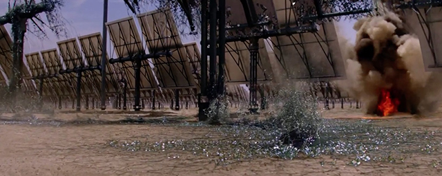
Frame from Transcendence.
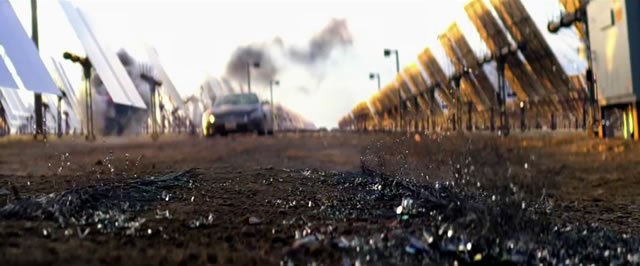
Frame from Transcendence.
I was curious about these images and then decided to recreate something similar, but I wanted to do it in a simpler and quicker way. I found out that combining Cinema 4D and Maya is probably the easiest way to create this effect.
If you have any clue to do the same in Modo or Softimage, please let me know, I'm really curious.
This is my current approach.
In Cinema 4D create a plane with a lot of subdivisions. Each one of those subdivisions will generate a cube. In this case I’m using a 1000cm x 1000cm plane with 500 subdivisions.
Create a new material and assign it to the plane.
Select the plane and go to the menu Simulate -> Hair objects -> Add hair.
If you zoom in you will see that one hair guide is generated by each vertex of the plane.
In the hair options reduce the segments guides to 1 because we just need straight guides we don’t care about hair resolution.
Also change the root to polygon center. Now the guides growth from each polygon center instead of each vertex of the plane.
Remove the option render hair (we are not going to be rendering hairs) from the generate tab. Also switch the type to square.
Right now we can see cubes instead of hair guides, but they are so thin.
We can control the thickness using the hair material. In this case I’m using 1.9 cm
Next thing would be randomising the height. Using a procedural noise would be enough to get nice results. We can also create animations very quickly, just play with the noise values.
Remove the noise for now. We want to control the length using a bitmap.
Also hide the hair, it’s quicker to setup if we don’t see the hair in viewport.
In the Plane material, go to luminance and select a bitmap. Adjust the UV Mapping to place the bitmap in your desired place.
In the hair material, use the same image for the length parameter.
Copy the same uv coordinates from the plane material.
Add a pixel effect to the texture and type the number of pixels based on the resolution of the plane. In this case 500
Do this in both materials, the plane and the hair. Now each cube will be mapped with a small portion of the bitmap.
Display the hair system and voila, that’s it.
Obviously the greater contrast in your image the better. I strongly recommend you to use high dynamic range images, as you know the contrast ratio is huge compared with low dynamic images.
At this point you can render it here in C4D or just export the geometry to another 3D software and render engine.
Select the hair system and make it editable. Now you are ready to export it as .obj
Import the .obj in your favourite 3D software. Then apply your lighting and shaders, and connect the image that you used before to generate the hair system. Of course, you can control the color of the hair system using any other bitmap or procedurals.
In order to keep this work very simple, I’m just rendering a beauty pass and an ambient occlusion pass, but of course you can render as many aov’s as you need.
I also animate very quickly the translation of the hair system and added motion blur and depth of field to the camera to get a more dynamic image, but this is really up to you.
This is just the tip of the iceberg, with this quick and easy technique you can create beautiful images combining it with your expertise.
Photography assembly for matte painters /
In this post I'm going to explain my methodology to merge different pictures or portions of an environment in order to create a panoramic image to be used for matte painting purposes. I'm not talking about creating equirectangular panoramas for 3D lighting, for that I use ptGui and there is not a better tool for it.
I'm talking about blending different images or footage (video) to create a seamless panoramic image ready to use in any 3D or 2D program. It can be composed using only 2 images or maybe 15, it doesn't matter.
This method is much more complicated and requires more human time than using ptGui or any other stitching software. But the power of this method is that you can use it with HDR footage recorded with a Blackmagic camera, for example.
The pictures that I'm using for this tutorial were taken with a nodal point base, but they are not calibrated or similar. In fact they don't need to be like that. Obviously taking pictures from a nodal point rotation base will help a lot, but the good thing of this technique is that you can use different angles taken from different positions and also using different focal and different film backs from various digital cameras.
- I'm using these 7 images taken from a bridge in Chiswick, West London. The resolution of the images is 7000px wide so I created a proxy version around 3000px wide.
- All the pictures were taken with same focal, same exposure and with the ISO and White Balance locked.
- We need to know some information about these pictures. In order to blend the images in to a panoramic image we need to know the focal length and the film back or sensor size.
- Connect a view meta data node to every single image to check this information. In this case I was the person who took the photos, so I know all of them have the same settings, but if you are not sure about the settings, check one by one.
- I can see that the focal length is 280/10 which means the images were taken using a 28mm lens.
- I don't see film back information but I do see the camera model, a Nikon D800. If I google the film back for this camera I see that the size is 35.9mm x 24mm.
- Create a camera node with the information of the film back and the focal length.
- At this point it would be a good idea to correct the lens distortion in your images. You can use a lens distortion node in Nuke if you shot a lens distortion grid, or just do eyeballing.
- In my case I'm using the great lens distortion tools in Adobe Lightroom, but this is only possible because I'm using stills. You should always shot lens distortion grids.
- Connect a card node to the image and remove all the subdivisions.
- Also deactivate the image aspect to have 1:1 cards. We will fix this later.
- Connect a transfer geo node to the card, and it's axis input to the camera.
- If we move the camera, the card is attached to it all the time.
- Now we are about to create a custom parameter to keep the card aligned to the camera all the time, with the correct focal length and film back. Even if we play with the camera parameters, the image will be updated automatically.
- In the transform geo parameters, RMB and select manage user knobs and add a floating point slider. Call it distance. Set the min to 0 and the max to 10
- This will allow us to place the card in space always relative to the camera.
- In the transform geo translate z press = to type an expression. write -distance
- Now if we play with the custom distance value it works.
- Now we have to refer to the film back and focal length so the card matches the camera information when it's moved or rotated.
- In the x scale of the transform geo node type this expression (input1.haperture/input1.focal)*distance and in the y scale type: (input1.vaperture/input1.focal)*distance being input1 the camera axis.
- Now if we play with the distance custom parameter everything is perfectly aligned.
- Create a group with the card, camera and transfer geo nodes.
- Remove the input2 and input3 and connect the input1 to the card instead of the camera.
- Go out of the group and connect it to the image. There are usually refreshing issues so cut the whole group node and paste it. This will fix the problem.
- Manage knobs here and pick the focal length and film back from the camera (just for checking purposes)
- Also pick the rotation from the camera and the distance from the transfer geo.
- Having these controls here we won't have to go inside of the group if we need to use them. And we will.
- Create a project 3D node and connect the camera to the camera input and the input1 to the input.
- Create a sitch node below the transfer geo node and connect the input1 to the project3D node.
- Add another custom control to the group parameters. Use the pulldown choice, call it mode and add two lines: card and project 3D.
- In the switch node add an expression: parent.mode
- Put the mode to project 3D.
- Add a sphere node, scale it big and connect it to the camera projector.
- You will se the image projected in the sphere instead of being rendered in a flat card.
Depending on your pipeline and your workflow you may want to use cards or projectors. At some point you will need both of them, so is nice to have quick controls to switch between them
In this tutorial we are going to use the card mode. For now leave it as card and remove the sphere.
- Set the camera in the viewport and lock it.
- Now you can zoom in and out without loosing the camera.
- Set the horizon line playing with the rotation.
- Copy and paste the camera projector group and set the horizon in the next image by doing the same than before; locking the camera and playing with camera rotation.
- Create a scene node and add both images. Check that all the images have an alpha channel. Auto alpha should be fine as long as the alpha is completely white.
- Look through the camera of the first camera projector and lock the viewport. Zoom out and start playing with the rotation and distance of the second camera projection until both images are perfectly blended.
- Repeat the process with every single image. Just do the same than before; look through the previous camera, lock it, zoom out and play with the controls of the next image until they are perfectly aligned.
- Create a camera node and call it shot camera.
- Create a scanline render node.
- Create a reformat node and type the format of your shot. In this case I'm using a super 35 format which means 1920x817
- Connect the obj/scene input of the scanline render to the scene node.
- Connect the camera input of the scanline render to the shot camera.
- Connect the reformat node to the bg input of the scanline render node.
- Look through the scanline render in 2D and you will see the panorama through the shot camera.
- Play with the rotation of the camera in order to place the panorama in the desired position.
That's it if you only need to see the panorama through the shot camera. But let's say you also need to project it in a 3D space.
- Create another scanline render node and change the projection mode to spherical. Connect it to the scene.
- Create a reformat node with an equirectangular format and connect it to the bg input of the scanline render. In this case I'm using a 4000x2000 format.
- Create a sphere node and connect it to the spherical scanline render. Put a mirror node in between to invert the normal of the sphere.
- Create another scanline render and connect it's camera input to the shot camera.
- Connect the bg input of the new scanline render to the shot reformat node (super 35).
- Connect the scn/obj of the new scanline render and connect it to the sphere node.
- That's all that you need.
- You can look through the scanline render in the 2D and 3D viewport. We got all the images projected in 3D and rendered through the shot camera.
You can download the sample scene here.
Upcoming VFX films /
2014
- Deliver Us From Evil 07/02/2014
- Dawn of the Planet of the Apes 07/11/2014
- I Origins 07/18/14
- Mood Indigo 07/18/14
- Hercules 07/25/2014
- Lucy 07/25/2014
- Guardians of the Galaxy 08/01/2014
- Into the Storm 08/08/2014
- Teenage Mutant Ninja Turtles 08/08/2014
- James Cameron's Deepsea Challenge 3D 08/08/2014
- The Giver 08/15/2014
- As Above, So Below 08/15/2014
- Ragnarok 08/15/2014
- Sin City: A Dame to Kill For 08/22/2014
- The Congress 08/29/2014
- The Zero Theorem 09/19/14
- The Maze Runner 09/19/2014
- The Boxtrolls 09/26/2014
- Gone Girl 10/03/2014
- Left Behind 10/03/2014
- The Interview 10/10/2014
- Birdman 10/17/14
- Dracula Untold 10/17/2014
- Kingsman: The Secret Service 10/24/2014
- Horns 10/31/14
- Interstellar 11/07/2014
- Fury 11/14/2014
- The Hunger Games: Mockingjay - Part I 11/21/2014
- The Imitation Game 11/21/2014
- The Pyramid 12/09/2014
- Exodus: Gods and Kings 12/12/2014
- The Hobbit: The Battle of the Five Armies 12/17/2014
- Annie 12/19/14
- Night at the Museum: Secret of the Tomb 12/19/2014
- Into the Woods 12/25/2014
- Paddington 12/25/2014
- Unbroken 12/25/2014
- Harbinger Down 2014
- Space Station 76 2014
2015
- Kitchen Sink 01/09/2015
- Inherent Vice 01/09/2015
- The Man From U.N.C.L.E. 01/16/2015
- Cyber 01/16/2015
- Ex Machina 01/23/2015
- Black Sea 01/23/2015
- Seventh Son 02/06/2015
- Jupiter Ascending 02/06/2015
- Poltergeist 02/13/2015
- Selfless 02/27/2015
- Chappie 03/06/2015
- Heart of the Sea 03/13/2015
- Cinderella 03/15/2015
- Insurgent 03/20/2015
- Fast and Furious 7 04/10/2015
- Avengers: Age of Ultron 05/01/2015
- Mad Max: Fury Road 05/15/2015
- Pixels 05/15/2015
- Tomorrowland 05/22/2015
- Untitled Cameron Crowe Project 05/29/2015
- San Andreas 06/05/2015
- Jurassic World 06/12/2015
- The Fantastic Four 06/19/2015
- Ted 2 06/26/2015
- Terminator: Genesis 07/01/2015
- Pan 07/17/15
- Ant-Man 07/17/2015
- Victor Frankenstein 10/02/15
- The Walk 10/02/15
- The Jungle Book 10/09/15
- Crimson Peak 10/16/2015
- The Hunger Games: Mockingjay - Part 2 11/20/2015
- Star Wars: Episode VII 12/18/2015
- The Lobster 2015
2016
- Gods of Egypt 02/12/2016
- Warcraft 03/11/2016
- Batman v Superman: Dawn of Justice 05/06/2016
- Captain America 3 05/06/2016
- The Sinster Six 11/11/2016
- Avatar 2 December 2016